
Home automation is one of the most popular DIY electronics projects nowadays. Imagine controlling all the electronic appliances in your home using your mobile or smartphone. You can control your lights, fans, fridge, AC, microwave, toaster, and even your doorbell with just a click or by programming them to work in a specific manner or at a particular time. Sounds interesting? Then let’s jump to the topic.
Here we will try to make it simple. That’s why we automate only one light and one fan. And also, please do read the remarks and conclusion at the end of this article.
Hardware Required:
In this project, the main component which we are going to use is the HC-05 Bluetooth module. We will also need a microcontroller to control all the operations. For that, we are going to use Arduino UNO. But you can use other boards like Mega, Nano, Mini, etc. Next, we will need a smartphone to control all the appliances. Next, we will need a relay module to turn on and off the appliances. The number of channels or relays in the module depends on the number of appliances you want to control. For simplicity, we are going to use a 2-channel relay module. Apart from all these, we will also need a breadboard and some jumper wires for connections.
Software Required:
To program the system, we will need Arduino IDE with the SoftwareSerial.h library. Usually, it is preinstalled in Arduino IDE. We will also use the Blynk app to control the appliances through smartphones. Apart from that we also need to install the Blynk library for Arduino. To install blynk library, just follow the steps mentioned in our ‘smart dustbin’ article.
Circuit Diagram:
Let’s discuss the connections one by one.
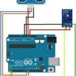
- VCC and GND pin of the Bluetooth module is connected to the 5V and GND pin of Arduino respectively. The TX pin of Bluetooth is connected to the RX pin of Arduino and the RX pin of Bluetooth is connected to the TX pin of Arduino. The rest of the pins of the Bluetooth module are remained open.
- VCC and GND of the relay module are connected to the 5V and GND pin of Arduino respectively. IN1 and IN2 pin of the relay is connected to D6 and D5 pin of the Arduino respectively.
- Now connections for the light and fan. We are taking light and fan which are operated in 220 to 230V. So one wire(preferably -ve or neutral wire) of the power supply is connected to the light and the other wire(preferably +ve or phase) is cut and one end is connected to the common pin of a relay and the other end is connected to NO(Normally Opened) pin of the relay. The same is done for the fan keeping it parallel with light.
To summarize all these connections, we have given a circuit diagram below.

Setting Up Blynk App:
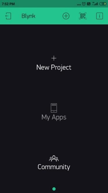
We are going to use the Blynk app to control the operation. So first we need to download the app from Playstore(for Android user) or Appstore(for iOS user). Now let’s set up the app.
- Create an account and Login.

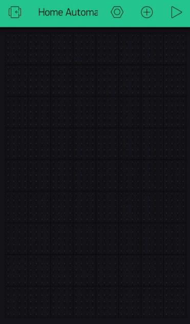
- Create new project
- Name that project “Home Automation” and fill this information. You shall also get a token in your email. Keep that authentication token.

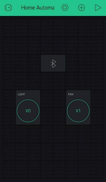
- Now click on the plus icon and add one Bluetooth widget and two buttons.
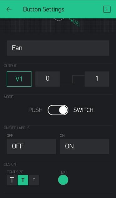
- Click on the first button and apply these parameters. Name the button as ‘Light’, in case of PIN add virtual pin V0, select the ‘Switch’ option instead of ‘Push’. Do the same for the other button and just change the name to ‘Fan’ and PIN to V1.

- Arduino Code:
#define BLYNK_USE_DIRECT_CONNECT
#include <SoftwareSerial.h>
SoftwareSerial BT(0, 1); // RX, TX

#define BLYNK_PRINT BT
#include <BlynkSimpleSerialBLE.h>

const int IN1 = 6;// Input for channel 1(Light)
const int IN2 = 5;// Input for channel 2(Fan)
int light,fan;

// You should get Auth Token in the Blynk App
char auth[] = "YourAuthToken"; //Place the authentication token you got from the e-mail.

void setup()
{
  BT.begin(38400); //For HC-05 default speed is 38400
  pinMode(IN1, OUTPUT);
  pinMode(IN2, OUTPUT);

  // Blynk will work through Serial
  // Do not read or write this serial manually in your sketch
  Serial.begin(38400);
  Blynk.begin(Serial, auth);

  digitalWrite(IN1, LOW);
  digitalWrite(IN2, LOW);
}

BLYNK_WRITE(V0){
  light = param.asInt();
}
BLYNK_WRITE(V1){
  fan = param.asInt();
}

void loop()
{
  Blynk.run();
  //Control relay channel 1 based on value of variable 'Light'
  if(light == 1){
    digitalWrite(IN1, HIGH);
  }else{
    digitalWrite(IN1, LOW);
  }

  //Control relay channel 2 based on value of variable 'Fan'
  if(fan == 1){
    digitalWrite(IN2, HIGH);
  }else{
    digitalWrite(IN2, LOW);
  }
}
Remarks & Conclusion:
- The number of controllable appliances depends on the number of relays in the module and the number of I/O pins available in the Arduino board. In Arduino Mega, you get a greater number of pins than UNO, Nano, and Mini so you can control more appliances with it.
- We have taken 5V relays here. As we are working with only one light and one fan, we can power the module using Arduino. But for a large number of appliances, we suggest you give an external 5V power supply to the relay module.
- While setting up the Blynk app, remember you get a limited amount of credit which limits the number of buttons you can add. Though you can buy more credit.
- We have mentioned that you can program your appliances to work at a specific time, but sadly this cannot be done using the Blynk app. You will need some third-party apps to do that.
Hope that you are clear with the Home Automation tutorial. If you face any difficulty please feel free to comment below. The comment box is always open for you. Will be soon with one interesting tutorial.