
School life is one of the most precious times of our lives. But one of the most annoying moments of school life was when the school bell didn’t ring even when the class time was over. And if this happened during the last period of the day, then, the frustration would have been on a different level. So, in this article, we are going to describe how you can make your own Automated School Bell using Arduino so that you can save yourself from extra time in class. And if you have passed your school already then this might help your sibling, cousin, or maybe your neighbor. You can also use this project in your home for different purposes. So, let’s start.
Components Required
Hardware Requirement:
So, first, we will need an Arduino. We will be using Arduino UNO but you can choose other Arduino boards as well. But boards like Arduino Lilypad are not preferred. Next, we will need an RTC or Real Time Clock Module. Because delay in Arduino is not as accurate as RTC Modules. We shall use the DS1307 RTC Module. But there are other alternatives available as well. Then we will need a 16×2 LCD to show the time and a Potentiometer to control its contrast. Next, we need a speaker or a buzzer or an Electric Bell. Also, a Relay module if you are using a high-power speaker or bell. For the sake of simplicity, we’ll be using an Arduino Buzzer. Next, we need a Breadboard and some Jumper Wires to place and connect the components.
DS1307 RTC Module:
As we have said before, the delay we get using a microcontroller is not accurate. That is why we have to use an RTC module for applications like Clock, Alarms, etc. DS1307 RTC Module is an accurate Real Time Clock Module. It is also one of the popular and one of the cheapest RTC modules. It uses a 12C communication protocol and works with 5V.

Software Requirement:
As for speaking of software, we’ll need Arduino IDE with the LiquidCrystal library installed. We shall use the RTClib.h library by Adafruit for our DS1307 RTC module. So if you have not installed it yet, follow these instructions:
- Open the Arduino IDE.
- Go to Sketch → Include Library → Manage Libraries. Or press ctrl+shift+I.
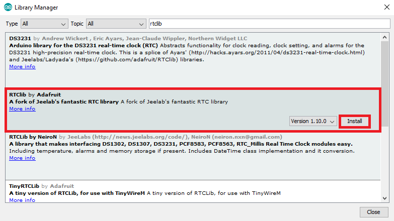
- The Library Manager window will open.
- In the search bar type “rtclib” and choose RTClib by adafruit. Then click on install.
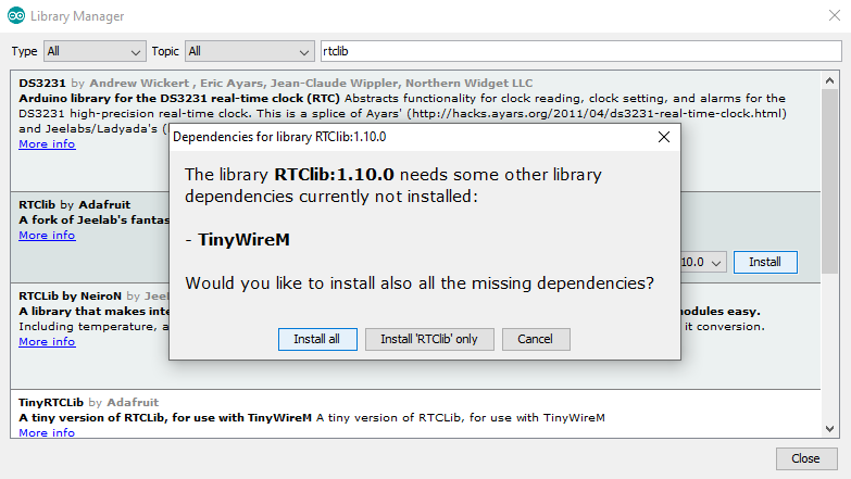
- Then you need to install some additional libraries as well so click on ‘install all’.
Now you have installed RTClib. We shall also need the Wire.h library as the RTC module follows 12C protocol. But usually this library is preinstalled in Arduino IDE.
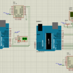
Circuit Diagram:
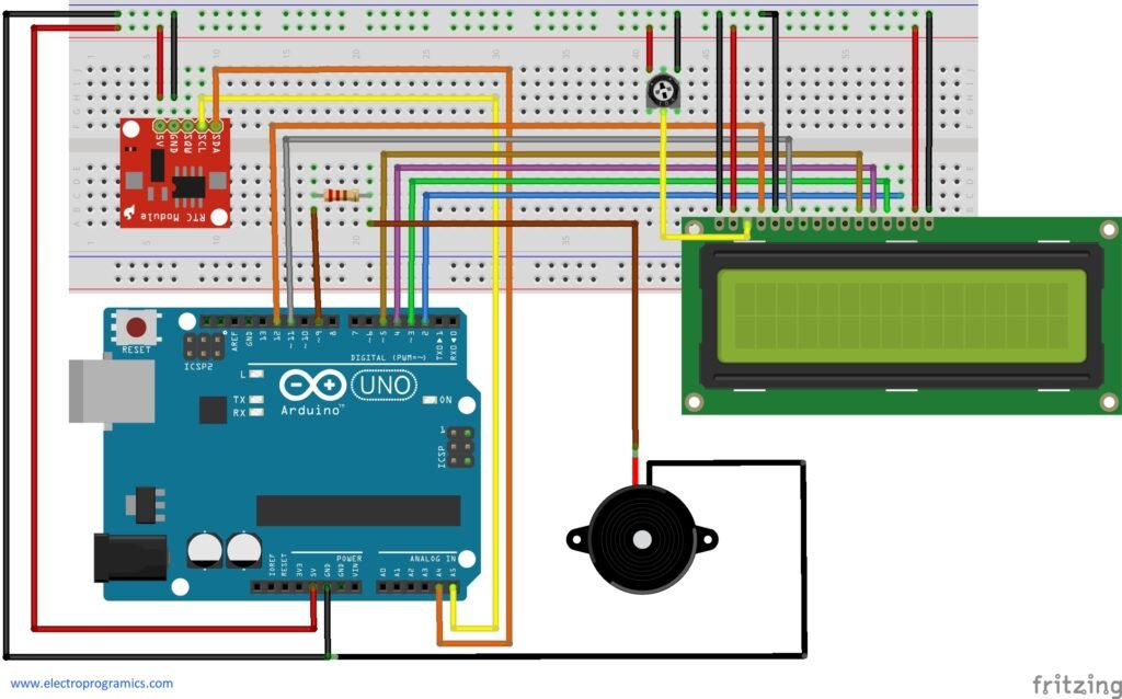
- Let’s first discuss the connections of the DS1307 RTC module. The VCC pin is connected to 5V. The GND pin is connected to ground. The SCL pin is connected to the 12C clock SCL pin on Arduino which, in case of UNO, is A5. Similarly, the SDA pin is connected to the 12C data SDA pin on Arduino which, in the case of UNO, is A4. (Remember: SDA and SCL pins are different for different Arduino boards.)
- Now let’s discuss the connection of LCD. Pin D4, D5, D6, D7 of LCD are connected to the pin D5, D4, D3, D2 of Arduino respectively. The enable pin of LCD is connected to the pin D11 of Arduino. RS pin of LCD is connected to the D12 pin of Arduino. VSS and RW pins of LCD are connected to the ground. VDD pin is connected to 5V. VEE pin is connected to Potentiometer. VCC and GND pin is connected to 5V and ground respectively.
- In case of the Potentiometer, the variable end or variable pin is connected to the VEE pin of LCD. One of the fixed pins is connected to the 5V and another is connected to the ground.
- The positive terminal of the buzzer is connected to the pin 9 of Arduino with a 220 Ohm resistor. And the other terminal is connected to the ground.
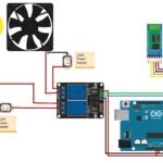
To summarize the connections, we have provided an image below:
Explanation of Circuit:
Now let’s discuss the connections. The SCL and SDA pins of RTC are connected to A5(SCL pin of Arduino) and A4(SDA pin of Arduino) respectively. The Arduino uses these pins to read time from RTC and also to adjust the time of RTC when needed. Next, the LCD is connected as per the instructions of ‘Hello World’ example of the LiquidCrystal library. The potentiometer is used to control the contrast of LCD. Now when the time in RTC matches the time at which the alarm should ring, the output at pin 9 becomes high and the buzzer or the electrical bell starts ringing.
Arduino Code:
// Date and time functions using a DS1307 RTC connected via I2C and Wire lib
#include "RTClib.h"
#include <Wire.h>
#include <LiquidCrystal.h>

const int rs = 12, en = 11, d4 = 5, d5 = 4, d6 = 3, d7 = 2;
LiquidCrystal lcd(rs, en, d4, d5, d6, d7);
RTC_DS1307 rtc;

char daysOfTheWeek[7][12] = {"Sunday", "Monday", "Tuesday", "Wednesday", "Thursday", "Friday", "Saturday"};

void PrintTwoDigits();
void showTime();

void setup () {
  Serial.begin(9600);
  pinMode(9,OUTPUT);
  lcd.begin(16,2);
  if (! rtc.begin()) {
    Serial.println("Couldn't find RTC");
    Serial.flush();
    abort();
  }

  if (! rtc.isrunning()) {
    Serial.println("RTC is NOT running, let's set the time!");
    rtc.adjust(DateTime(F(__DATE__), F(__TIME__)));

  }
}
void loop () {
    DateTime now = rtc.now();
    showTime();

    if(now.hour()==16 && now.minute()==51 && now.second()==00
    ||now.hour()==16 && now.minute()==51 && now.second()==10){
      lcd.clear();
      lcd.setCursor(0,0);
      lcd.print("BELL RING");
      digitalWrite(9,HIGH);
      delay(5000);
      digitalWrite(9,LOW);
      lcd.clear();
    }
}
void PrintTwoDigits(int number){
  if(number<10){
    lcd.print("0");
  }
  lcd.print(number);
}
void showTime(){
    DateTime now = rtc.now();
    lcd.setCursor(0,0);
    lcd.print("Time:");
    lcd.setCursor(0,1);
    PrintTwoDigits(now.hour());
    lcd.print(':');
    PrintTwoDigits(now.minute());
    lcd.print(':');
    PrintTwoDigits(now.second());
}
Explanation of Code:
In the first 3 lines of the code we have included ‘RTClib’, ‘Wire’ and ‘LiquidCrystal’ library. Then we have set up the LCD. Next, we have created an DS1307 RTC object named ‘rtc’. Then we have created two functions – PrintTwoDigits() and showTime(). PrintTwoDigits() functions turns single digits like 1,2,3,4 etc into double digits like 01,02,03,04 etc. And showTime() displays the text ‘Time:’ and the actual time on LCD.
In the setup() function we have set pin 9 of the Arduino as an output pin. We also started the LCD using setup() function. Next, we have two if statements. The first one “if (! rtc.begin())” checks whether the RTC has begun or not. If not then it prints “Couldn’t find RTC” on the serial monitor. The second one, “if (! rtc.isrunning())” checks if the RTC has been initialized or not. If not then it sets the time as it is on the computer.
Next in the loop() function we set the value of ‘now’ to the value of date and time in RTC using rtc.now(). Then we call the showTime() function to print time on LCD. Next we have an if statement in which we have given the time as condition at which the bell will ring. In this case it is 16:51:00 and 16:51:10. When the condition is matched with RTC time, the LCD prints ‘BELL RING’ and the output pin 9 becomes high. So the bell starts ringing. This happen for 5 seconds then output pin 9 will become low until the next condition is matched.
Note:
- When the 3V battery of the RTC module becomes dead you just need to connect the Arduino to the computer and upload the code again to reset the time.
- If you attach a relay then there will be no change in code as long as the output in is 9.
Conclusion
Hope that the tutorial Automatic School Bell using Arduino is clear. If you have any doubts please feel free to ask below in the comment box which is always open for you. Thank you and will be back with another interesting tutorial soon.